Summary
MAGNET_GENERAL_CATALOG_2019
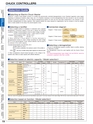
CHUCK CONTROLLERSELECTROMAGNETICCHUCKPERMANENTPERMANENTCHUCKSCONTROLLERSMAGNETIC CHUCKS ELECTROMAGNETIC CHUCKSBLOCKSFOR MCVACUUMCHUCKSPROMELTA*SYSTEMSINE BARCHUCKSBLOCKS, HOLDERS,MINI CHUCKSHOLDINGTOOLSMEASURING MAGNETICTOOL HOLDERS HOLDERSMAGNETICTOOLS19Selection Guide■Selecting an Electro Chuck MasterKANETEC’s Electro Chuck Master consists of a rectifier and electronically controlled demagnetization circuit. Residual magnetism varies largelydepending on workpieces (material, shape, mass, etc.). It is therefore necessary to set the demagnetizing time (few seconds to over ten seconds)suitable for particular workpieces. The most effective demagnetizing patterns for each set time have been programmed in the computer to startautomatic demagnetization by button operation. After studying whether the output required for magnetization may be constant or must be variable,select a model suitable for the rating of the electromagnetic chuck.■Selecting a rectifier①Select a suitable rectifier for installation in combination with a separatedemagnetizer. (Connection diagram 2) Be sure to observe the followingconditions: Voltage of electromagnetic chuck≧output voltage of rectifierCurrent of electromagnetic chuck < output current of rectifier Electromagnetic chuck 90 VDC, 0.8 AOutput of rectifier 90 VDC, 1 A②When selecting a Chuck Master or rectifier dedicated todemagnetization having an output voltage exceeding the rated voltage(90 V) of the electromagnetic chuck, special attention must be paid tothe selection of the current capacity.〈Example〉Electromagnetic chuck 90 VDC, 4.5 ARectifier output 0 to 120 VWith the above combination, the maximum current of the rectifier is:120V4.5A×=6A, thus a rectifier having output capacity 5A cannot be used.90V③Other considerations should include fluctuation of the voltage in theoperation area. Select an output capacity with sufficient allowance.■Connection diagram■Selection based on electric capacity Name Model Power SourceElectroChuck MasterChuck Masterdedicated todemagnetizationSelector switchRectifierEH-V305AEH-VE305ASingle-phase100 VAC?220 VAC50/60 Hz■Selecting a demagnetizerThe use of a demagnetizer requires a rectifier. Select a rectifier, referringto“Selecting a rectifier.”The demagnetizer cannot be used together with the Electro ChuckMaster.The manual demagnetization types, Model S-2A and ESR-5A, cannot beconnected to equipment other than a rectifier.DC Output Demag.Chuck RatingRectifier DemagnetizerVoltage Current ControlVoltage Max. Current※5AEH-VE210D0?90 VDC 10A 9.0ASingle-phase 200 VACES-V220A 20A 18.0A50/60 HzAutoES-V230A 30ANot required27.0AES-M103BES-M305BESR-N102ESR-5AS-2ASingle-phase 100 VAC50/60 HzSingle-phase 100/200 VAC50/60 HzSingle-phase 100 VAC50/60 HzMax. 120 VDC50/60 HzMax. 120 VDC50/60 HzSingle-phase 100 VAC50/60 HzSingle-phase 100 VAC50/60 Hz90 VDCMax.120 VDC3A Not required2.7A90 VDC4.5A5A 4.5A2ADiagram 1 Power source→Diagram 2 Power source→Diagram 3 Power source→ElectroChuck masterOperation boxRectifierElectroChuck masterDemagnetizerChuck Master or selectorswitch dedicated todemagnetization1.8A4A Manual3.2AKR-N,KR-T2A 1.6AKR-N101A1AS-2A 0.9A90 VDCKR-N103A2.7A3A ?? ??KR-T203A10?120 VDC ESR-5A2.4ASingle-phase 100/200 VAC50/60 HzKR-T205 0?120 VDC 5A 4.0AChuckChuckChuckConnectionDiagram※The max. current of the applicable chuck must be the Chuck Master’s rated current×0.9 or less. However, for the output voltage 120V, the max. current must be rated current×0.8 or less.■Selection based on function NameElectro Chuck MasterChuck Master dedicated todemagnetizationRectifierModelFunction DC Output Demag. Control Chuck RatedCurrentRectifier circuit Demag. circuit Variable Invariable Auto ManualES-V◯◯◯??◯??