BookTitleMAGNET_GENERAL_CATALOG_2019
- page
- 27/188
This page is an overview of MAGNET_GENERAL_CATALOG_2019 on page27
Move to the page after second(s).
Now go to the page by clicking "Open the e-Book" button.
This page is an overview of MAGNET_GENERAL_CATALOG_2019 on page27
Move to the page after second(s).
Now go to the page by clicking "Open the e-Book" button.
MAGNET_GENERAL_CATALOG_2019
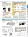
TBTrouble?If your electromagnetic chuck failed, refer tothis page. Symptoms, possible causes andcorrective actions of two typical Chuck Mastersare presented here. Please follow theseinstructions prior to asking for repair orpurchasing parts.EH-V305AES-M305B◇Residual holding power is large.●?Turn the demagnetization adjust variable resistor to apoint where the maximum demagnetization effect canbe obtained.◇Holding power is weak.●Set the excitation voltage adjust variable resistorat the maximum.●If the holding power is still weak, the magnet beingused may not be adequate for the shape, materialor holding direction of workpieces.※Note: Since ES-M Series outputs a constant excitation voltage, itdoes not have the excitation voltage adjust variable resistor.■If the Chuck Master does not function properly, check it referring to the following table.EH-V305ASymptom Electromagnetic Chuck MasterDemagnet- AlarmCheck andchuck does not does not Fuse blows. ization is not indicator lampCorrective ActionCausehold workpiece. output voltage.performed. lights up.Power is not being supplied.●●Check the power source.Fuse has blown.●●Remove the fuse from the fuseholder and replace it with a new one.Power source is exceedingthe rated voltage.Output voltage adjust variableresistor has been turned CCW fully.Wiring to electromagneticchuck has been brokenor shorted.Insulation ofelectromagnetic chuckand its wiring is poor(ground)ES-M305B/103BSymptom Electromagneticchuck does nothold workpiece.●※Note:・Prior to checking/investigating causes, be sure to turn off the power and disconnect the powercable from the Chuck Master.・Measure the insulation resistance of the electromagnetic chuck with an insulation resistancetester. Be sure it is above 5 M at a test voltage of 500 VDC.・If the electromagnetic chuck failed, place an appropriate warning (such as attaching a tag of“Outof Order. Use Prohibited.”). If the cause cannot be identified, please contact the manufacturer.●Check the power source voltage and usethe power source at the rated voltage.●●Adjust the output voltage again.●●●●●●●●Demagnet-Fuse blows. ization is notperformed.If measurement of resistance ofelectromagnetic chuck is∞Ω,wiring broken. If 0Ω, wiring shorted.Disconnect the cord from the outputterminal of Chuck Master and measureinsulation resistance of electromagneticchuck. OK when it is above 5 MΩ. Ifless than 5 MΩ, check wiring. Ifinsulation of electromagnetic chuck ispoor, please request for repair.Check and Corrective ActionCausePower is not being supplied.●Check the power source.Fuse has blown.●Remove the fuse from the fuse holder and replace it witha new one.Power source is exceedingthe rated voltage.Wiring between ChuckMaster and electromagneticchuck is defective orelectromagnetic chuck isfaulty.●●●●Check the power source voltage and use the powersource at the rated voltage.Disconnect the cord from the output terminal of ChuckMaster and measure insulation resistance ofelectromagnetic chuck. OK when it is above 5 MΩ. If lessthan 5 MΩ, check wiring. If insulation of electromagneticchuck is poor, please request for repair.ELECTROMAGNETICCHUCKSCHUCKCONTROLLERSPERMANENTMAGNETIC CHUCKSPERMANENTELECTROMAGNETIC CHUCKSBLOCKSFOR MCVACUUMCHUCKSModel TB TERMINAL BOXAn example of integrating wires by use of a terminal box②①Electro Chuck Master②Terminal box③Electromagnetic chucksconnected③①PROMELTA*SYSTEMSINE BARCHUCKSTB-6PCBLOCKS, HOLDERS,MINI CHUCKS[Application]When several electromagnetic chucks are connected and areto be controlled together by one unit of the Chuck Master, aterminal box is required that integrates wires from the chucks.Terminal boxes for 2 circuits up to 10 circuits are available.12011069INPUTOUT4 OUT3 OUT2 OUT1175185N.P.4-φ5.5〈TB?2PD/4PD〉〈TB?6PC?10PC〉※The number of“OUT”in the above figures varies according to the number of branches.INPUTW 1W 2W 3OUT1OUT2OUT3OUT41590120154-φ5.5100[mm(in)]ModelInput CapacityNo. ofDimensionsOutputs W? W? W?TB- 2PD2(See left-side figure)TB- 4PD4TB- 6PC30A6280(11.0)266(10.4)250(9.84)TB- 8PC8330(12.9)316(12.4)300(11.8)TB-10PC10380(14.9)366(14.4)350(13.7)〈An example of TB-2PD wiring〉INPUT(*1)Ground(*2)E21E21Ground(*2)Ground(*2)OUT2OUT1HOLDINGTOOLSMEASURINGTOOL HOLDERSMAGNETICHOLDERSMAGNETICTOOLS20