BookTitleMAGNET_GENERAL_CATALOG_2019

page
67/188

This page is an overview of MAGNET_GENERAL_CATALOG_2019 on page67
Move to the page after second(s).
Now go to the page by clicking "Open the e-Book" button.

MAGNET_GENERAL_CATALOG_2019

ReadBook

Open e-Book in Flash Viewer

This e-Book is not available in your environment.

Summary

MAGNET_GENERAL_CATALOG_2019

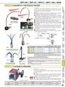
MPV-MF / MPV-CL / MPV-F / MPV / NH / MDRModel NH MAGNETIC TYPE NOZZLE HOLDERIncreased holding power!!NH-SH1 nozzle tip(flow rate adjustable)NH-SH1Flexible in all directions!!NH-M3An example of NH-M1 usage[Application]This holder is used to supply cutting fluid or air to machine tools. This canalso be used to remove chips and particles produced during electricdischarge machining by injecting cutting liquid.[Features]●Compared with conventional products, flexibility has been extremelyimproved. The flexible part can be bent freely. (NH-M1, M3)●By employing a metallic flexible part, the holding posture is maintainedstably even when releasing high pressure air or a large amount of cuttingfluid. In addition, it is highly resistant to thermal damage by chips and itsdurability has been improved. (NH-M1, M3)●The powerful magnet enables the holder to be mounted in any position easily.●The nozzle tip cab be positioned in any posture and at any angle.●The holder is equipped with a valve to enable adjustment of the flow rate.●The adjustable hose can be adjusted in length by removing or addingjoints. (NH-P)●The employment of a copper pipe flexible part has increased the holdingpower twice as large as the conventional model (NH-M1). The posture ofthe flexible part can be maintained even when releasing high pressureair. (NH-SH1)●The flow rate can be adjusted at the nozzle tip. (NH-SH1)●The flexible part can be mounted on a conventional magnet by using ascrew conversion joint. (NH-SH1)PS1/4PS1/8Ball valvePT1/4×φ9(hose nipple)Ball valvePT1/8×PF1/825.514 9Ball valvePT1/4×PF1/8ELECTROMAGNETICCHUCKSCHUCKCONTROLLERSPERMANENTMAGNETIC CHUCKSPERMANENTELECTROMAGNETIC CHUCKSBLOCKSFOR MC25.5NH-P1/NH-M1Details of thread sizeHose nipple(φ9)Ball valvePT1/8×PF1/8VACUUMCHUCKS3-PT1/8PT1/4ONOFFNH-P3Parts available individuallyNH-P1An example of usageNH-P1(Available separately)NH-M3Model MDR MAGNETIC DRESSERMDR-1CThe dresser is not included.Model Holding Power Nominal Size Inlet Dia. Hose Length No. of Outlets MassNH-P1 245N(25kgf)φ70(2.75)×27(1.06)390(15.3) 1 pc 0.95kg/2.1 lbNH-P3 490N(50kgf) 48(1.89)×73(2.87)×54(2.12) 420(16.5) 3 pcs 1.65kg/3.6 lbφ9NH-M1 245N(25kgf)φ70(2.75)×31(1.22) 400(15.7) 1 pc 0.9kg/1.9 lb(0.35)NH-M3 490N(50kgf) 48(1.89)×73(2.87)×54(2.12) 400(15.7) 3 pcs 1.9kg/4.1 lbNH-SH1 245N(25kgf)φ70(2.75)×31(1.22) 412(16.2) 1 pc 1kg/2.2 lb※Upper limit of pressure…Adjustable hose (NH-P1, P3) : Air pressure 0.34 MPa, liquid pressure 0.2 MPaMetallic flexible hose (NH-M1, M3, SH1): 0.6 MPa max. (Upper limit of flow rate: 10 liters/min. max. for NH-M1 & M3 and 3 liters/min. max. for NH-SH1) However, depending on releasing angles, the posture of thehose may be changed by a jetting pressure even when the air/liquid pressure is below the upper limit. Insuch a case, turn the valve to reduce the flow rate.※The hose length includes the stainless steel nozzle part (NH-P: 70 mm) at the tip.※The holding power is based on a test piece of SS400, 10 mm thick, ground surface.※The magnet section of NH-M and NH-P is common. Therefore the upper section is interchangeable for mounting between NH-M andNH-P.※The magnet section of NH-SH1 is common with NH-M1 and NH-P1 and therefore, the upper section is interchangeable for mounting.However, for installation of NH-SH1 flexible hose on NH-P1 and M1, a screw conversion joint needs to be procured separately.※NH-M1, M3 flexible part dia.:φ11 mm, NH-SH1 flexible part dia.:φ9 mm※Copper pipe is used for the NH-SH1 flexible part and therefore this model must not be used in liquids containing components thatcorrode copper.※The NH-SH1 flexible part cannot be used in applications where it is bent more than 90 degrees or flexed repeatedly in the samepoint as such operations will damage the copper pipe.Holdingpower800NNH-P3/NH-M3 Details of thread size[mm(in)][Application]A dressing tool for grinding wheels.The dresser can be held firmly on a powerful magnetic holder base. Settingup is easy and reliable.[Features]●The magnetic force can be turned on and off with the lever to facilitatemounting to and demounting from the machine table.(For setting on amagnetic chuck, power OFF the chuck and power ON this Dresser.)●The dresser can be mounted at any angles.●The dresser mounting clamp can be secured to either the side or the top ofthe magnetic holder base. (The photo shows the clamp mounted on the side.)DimensionsModelHolding PowerWidthLengthHeightDresser Shaft Dia.MassMDR-1C800N(80kgf)50(1.96)58.5(2.30)55(2.16)φ11(0.43)andφ12(0.47)1.2kg/2.64 lbNH-M3[mm(in)]PROMELTA*SYSTEMSINE BARCHUCKSBLOCKS, HOLDERS,MINI CHUCKSHOLDINGTOOLSMEASURINGTOOL HOLDERSMAGNETICHOLDERSMAGNETICTOOLS60